Under the hood: The administrative state of Linux network interfaces

Recently we were wondering why node_exporter, in all the nice metrics it exposes about a Linux system, does not show if a Linux network interface is configured to be UP or DOWN, but only the operational state. So we started digging…

On the CLI, using iproute2 tooling, the operational state is shown explicitly, for example in the 2nd column in the following output:

$ ip -br l

lo UNKNOWN 00:00:00:00:00:00 <LOOPBACK,UP,LOWER_UP>
eth0 DOWN aa:bb:cc:dd:ee:ff <NO-CARRIER,BROADCAST,MULTICAST,UP>
wlan0 UP 00:08:15:ab:cd:ef <BROADCAST,MULTICAST,UP,LOWER_UP>
eth1 DOWN 01:31:17:00:47:11 <BROADCAST,MULTICAST>
ffho-ops UNKNOWN <POINTOPOINT,MULTICAST,NOARP,UP,LOWER_UP>

If you look closely you can see that the administrative state is encoded within the last column, namely it’s up if the keyword “UP” is part of the list, and down otherwise.

We started digging through /sys/class/net/* but didn’t find any entry which seemed to correspond to the administrative state of the interface. Digging further the flags caught my eye and playing with an interface revealed that the last bit seemed to indicate if the interface should be UP or DOWN.

While crafting a small PR for node_exporter I dug further to figure out why that is. The first stop was the Linux Kernel cross reference, which revealed the flags seem to stem from BSD. Searching for those yielded the netdevice(7) man page containing a definition for the flags:

SIOCGIFFLAGS, SIOCSIFFLAGS
Get or set the active flag word of the device.
ifr_flags contains a bit mask of the following values:

Device flags
IFF_UP Interface is running.
IFF_BROADCAST Valid broadcast address set.
IFF_DEBUG Internal debugging flag.
IFF_LOOPBACK Interface is a loopback interface.
IFF_POINTOPOINT Interface is a point-to-point link.
IFF_RUNNING Resources allocated.
...

Now it all makes sense, and hopefully soon everyone can just check the adminstate of Linux networking interfaces in Prometheus 🙂

Update (May 2023): The PR has been merged.

Influencing Linux Source Address Selection on routes installed by bird and FRR

The use of dynamic routing protocols – mainly IS-IS, OSPF and BGP – is quite common in contemporary networks, even on the host networking stacks. In some situations it is desirable to not only control the path packets will take to any given destination, but also the source address of locally sourced traffic.

By default Linux systems will use the primary IP address of the egress interfaces, which has global scope and has the same address family of the flow in question. This decision can be overridden per destination by setting the src attribute of a route to a specific locally configured IP address, for example:

ip route add 2001:db8:0815::/48 via 2001:db8:1::1 src 2001:db8::42

For routes installed by a routing daemon this has to happen inside the routing daemon, so the the NETLINK call will know about the source address to set. For bird this is rather straight forward, for FRR it took me – and apparently others – a bit of time to find the right knobs, so I’ll document both ways here for future me and – likely – present you looking for it 🙂

bird

In bird that’s fairly simple and can be done via the export filter of protocol kernel. In bird 1 this could look like this:

define LO_IP = 192.0.2.42;

protocol kernel {
scan time 20;
import none;
export filter {
# <Apply any required filtering here/>

# Set src attr of all routers installed in FIB to LO_IP
krt_prefsrc = LO_IP;
accept;
};
}

For bird 2 this has to happen inside the address family specific configuration:

define LO_IP = 2001:db8::42;

protocol kernel {
scan time 20;

ipv6 {
import none;
export filter {
# <Apply any required filtering here/>

# Set src attr of all routers installed in FIB to LO_IP
krt_prefsrc = LO_IP;
accept;
};
}

FRR

For FRR the configuration is a little bit more involved and requires a route-map to be applied to the protocols the routes are learned from! So if you want to set the source address for routes learned from OSPF this would look like this:

route-map set-loopback-src-ip permit 1
set src 192.0.2.42
!
ip protocol ospf route-map set-loopback-src-ip

If you want to filter on which prefixes this applies, this could be done by adding a prefix list into the route-map, e.g.

route-map set-loopback-src-ip permit 1
match ip address prefix-list YOUR_PREFIX_LIST
set src 192.0.2.42

If you run OSPF + BGP and want the source address to be set for both protocols, you need to add an additional line to the config example from above:

ip protocol bgp route-map set-loopback-src-ip

Hardware platforms of a Freifunk network

This post is part of the series Building your own Software Defined Network with Linux and Open Source Tools and covers the hardware platforms used within the backbone network infrastructure.

In the early days into the project we didn’t have much funds but thankfully received quite some donations in terms of old hardware as well as money. As we were young and didn’t know what we know today, we went down quite some different roads, made lots of experiences along the way, eventually reaching the setup we have today. This posts lists most the platforms we used within the last years, basically only leaving out early wireless platforms and sponsored server machines.

As most Freifunk communities rely heavily on products from the portfolio of Ubiquiti Networks, quite some devices will be covered. In the following I will just call them ubnt.

Continue reading Hardware platforms of a Freifunk network

Modelling (C)WDM MUXes in NetBox/Nautobot – the universal way

A while ago we had a discussion in #DENOG on how to best model CWDM MUXes in NetBox/Nautobot, so they can be used to build a network topology, which can be leveraged for holistic automation, and are prepared for augments, repairs and network changes.

8Ch CWDM MUX

“Natural” way of modelling

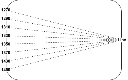
The “natural” way of modelling for example an 8Ch CWDM MUX – as shown above – would be do create a DeviceType containing one RearPort with 8 positions as well as 8 FrontPorts which map to one position each. So logically this would look like the following

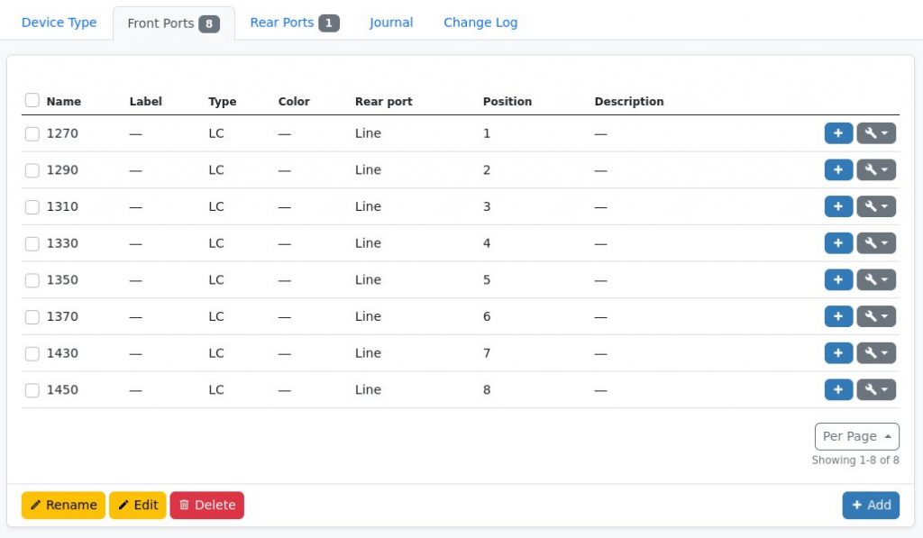
Inside NetBox the Rear Port and Front Ports view of the DeviceType could look like this

One Rear Port with 8 positions
Eight Front Ports mapped to one position each

This model absolutely works, allows tracing connections through the MUXes etc. as long as we always use exactly the same MUX on both ends of the fiber for a given WDM setup.

Limitations

If one MUX would decay over time and needs to be replaced by another model e.g. due to supply chain issues, this might get tricky. If the new MUX for example had 10 channels and does not skip 1390 and 1410, the mapping would fail. This obviously would also be the case if, e.g. for an expansion, the setup should be changed to 18Ch MUXes and this could only be done one side after another.

Universal way of modelling

As the ITU CWDM standard only defines 18 CWDM channels in total with a fixed spacing of 20nm we can use one simple trick to overcome this limitation: Always define all 18 positions and only map the existing Front Ports to their associated position as shown in the following table.

PositionChannel
1
1270
21290
31310
41330
51350
61370
71390
81410
91430
101450
111470
121490
131510
141530
151550
161570
171590
181610

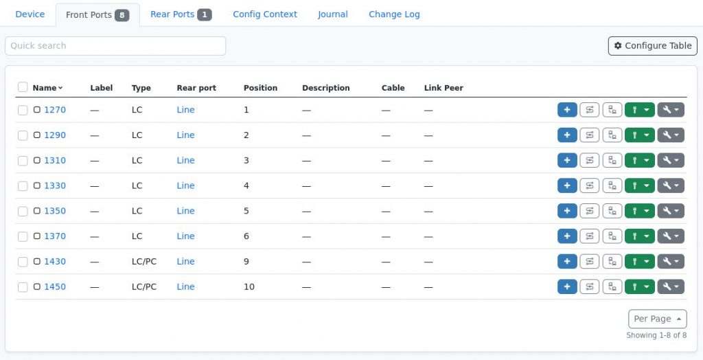
So the Front Ports of the MUX shown above would be mapped to positions 1-6, 9, and 10. This way all CWDM MUXes can be connected in NetBox/Nautobot and all channels which exist on both ends can be connected and traced through.

Eight Front Ports mapped to one their associate (existing) positions

What about DWDM?

For DWDM systems this obviously would be somewhat harder given the bigger amount of possible channels, especially when different spacing options (25, 50, 100GHz) are taken into account. It would be possible though to go for 160 positions and map the channels accordingly given strict adherence to a to be predefined map.