At DENOG13 I held a workshop Fun with PBR, VRFs and NetNS on Linux (in German) where I showcased forwarding IP packets within a VRF via static MPLS LSPs. I’ve been asked to publish the configuration for this lab, so here we are 🙂
Consider the following topology consisting of a core ring build with 5 routers, a border router (br-01) connected to core router E (cr-E) as well as to the Internet. All routers take part of OSPF area 0 and run iBGP with br-01 as the route reflector, which is providing a default route. This is the same setup used for most of the FrOSCon Network Track.
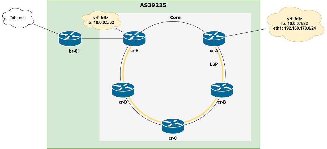
On top of that cr-A and cr-E have a VRF vrf_fritz configured with a loopback IP of 10.0.0.1/32 and 10.0.0.5/32 respectively, cr-A also has a directly connected subnet 192.168.178.0/24 which is also part of this VRF. A static LSP has been set up between cr-A and cr-E to transport all packets within VRF vrf_fritz via the “scenic route” meaning the long path cr-A <-> cr-B <-> cr-C <-> cr-D <-> cr-E instead of the direct connection cr-E <-> cr-E. Ok, so how does this work?
MPLS plumbing
For MPLS to work, we need three things
- The
mpls_iptunnelmodule must be loaded, therefore we just add it to/etc/modulesso it will be loaded on boot up net.mpls.platform_labelmust be set to the maximum label expected/allowed (-> /etc/sysctl.conf, set to 1000000)net.mpls.conf.$IFACE.inputmust be set to 1 for all interface where MPLS packets should be decapsulated
Setting the latter via /etc/sysctl.conf has the disadvantage that all interfaces have to be present when sysctl settings are applied to take effect. As in this setup only physical interface are used to transport MPLS encapsulated packets, this would most likely work. Nevertheless, and to be on the safe side ifupdown-ng’s MPLS support is leveraged to set this after interface turn-up. If you want to learn more about ifupdown-ng, see my DebConf talk. The interface configuration (of enp3s0 of cr-A for example) looks like the following:
auto enp3s0
iface enp3s0
         alias cr-B
         address 2001:db8:f0ab::a/64
         mtu 9216
         mpls-enable yes
Note that all transfer networks within this lab follow the schema of 2001:db8:f0XY::{X,Y} for any given routers X and Y, so the above prefix is configured the link between cr-A and cr-B on cr-A.
MPLS LSP
To set up the label switched paths, we use the Linux networkers Swiss army knife ip to add the appropriate routes. As MPLS basically boils down to three things – pushing, swapping or popping a label (stack) – we have to map those to ip routes. The MPLS used in the lab are of the format X0Y where X and Y are the numerical router IDs (A = 1, E = 5) for traffic from X to Y.
MPLS Push
On cr-A and cr-E we want to encapsulate packets in MPLS to follow the LSP to the other end, so we need to push a label on here. The following route is used on cr-A to route all non-local traffic from VRF vrf_fritz via the LSP:
ip route add 0.0.0.0/0 encap mpls 102 via inet6 2001:db8:f0ab::b vrf vrf_fritz
MPLS Swap
The encapsulated packets arriving on cr-B need to be forwarded to cr-C, cr-D and eventually cr-E, and we need a way back in the reverse direction as well. The following adds two routes to swap labels on cr-B to forward packets on the LSP from cr-E to cr-A and vice versa respectively:
ip -M route add 302 as 201 via inet6 2001:db8:f0ab::a
ip -M route add 102 as 203 via inet6 2001:db8:f0bc::c
MPLS Pop
To decapsulate packets and route them regularly, we add routes which just have the VRF interface as the destination device set. If we were not to use VRFs but wanted to route packets via the global routing table (GRT) we would just use lo as destination. The following is used on cr-E:
ip -M route add 405 dev vrf_fritz
Putting it all together
We obviously need two LSPs, one for each direction. To make sure the routes are installed after the interfaces are configured and taken down before the interfaces are deconfigured they are given as up/down commands on the interfaces in /etc/network/interfaces. The relevant stanzas look like this:
# cr-A

auto vrf_fritz
iface vrf_fritz
     address 10.0.0.1/32
     #
     vrf-table 1178
     #
     up    ip -M route add 201 dev vrf_fritz
     down  ip -M route del 201 dev vrf_fritz
     up    ip route add 0.0.0.0/0 encap mpls 102 via inet6 2001:db8:f0ab::b vrf vrf_fritz
     down  ip route del 0.0.0.0/0 encap mpls 102 via inet6 2001:db8:f0ab::b vrf vrf_fritz
# cr -B (cr-C + cr-D similar)

auto enp1s0
 iface enp1s0
     alias cr-A
     address 2001:db8:f0ab::b/64
     mtu 9216
     #
     mpls-enable yes
     up    ip -M route add 302 as 201 via inet6 2001:db8:f0ab::a
     down  ip -M route del 302 as 201 via inet6 2001:db8:f0ab::a
# cr-E

auto vrf_fritz
 iface vrf_fritz
     address 10.0.0.5/32
     #
     vrf-table 1005
     #
     up    ip -M route add 405 dev vrf_fritz
     down  ip -M route del 405 dev vrf_fritz
     down  ip route del 192.168.178.0/24 vrf vrf_fritz
     up    ip route add 192.168.178.0/24 encap mpls 504 via inet6 2001:db8:f0de::d vrf vrf_fritz
So does this all work?
Of course, it does! Setting up a network name space and shoving a USB NIC into it on my laptop allowed poking at this setup from a client’s point of view, which is connected to cr-A. The configuration on the client side is as straight forward as it gets:
root@sesquialtera:~# ip -br a
lo               DOWN
eth2             UP             192.168.178.10/24

root@sesquialtera:~# ip r
default via 192.168.178.1 dev eth2
192.168.178.0/24 dev eth2 proto kernel scope link src 192.168.178.10
fping shows that all expected internal IPs within the VRF are reachable but the Internet isn’t:
root@sesquialtera:~# fping 192.168.178.1 10.0.0.1 10.0.0.5 1.1.1.1
192.168.178.1 is alive
10.0.0.1 is alive
10.0.0.5 is alive
1.1.1.1 is unreachable
So how does an mtr look? It consists of a lot of ??? as the intermediate hops don’t know how to respond to the source.
$ mtr  10.0.0.5

Host
 192.168.178.1
 ???
 ???
 ???
 ???
 10.0.0.5
Leaking routes
Now how to connect the vrf_fritz to the Internet on cr-E? We have to leak the default route into the VRF as well as the client subnet into the GRT. The only way I got this working is by replicating the exact routes in the GRT/VRF table:
ip route add default vrf vrf_fritz via x.x.x.x dev enp2s0
ip route add 192.168.178.0/24 encap mpls 504 via inet6 2001:db8:f0de::d
It would have been nice to just add a route to the VRF which leaked the default route and shoved the packets into the GRT and vice versa, but I couldn’t get any stunts like that working. If I missed something here, please reach out and let me know!
Is the Internet working now?!
Of course:
root@sesquialtera:~# fping 192.168.178.1 10.0.0.1 10.0.0.5 1.1.1.1
192.168.178.1 is alive
10.0.0.1 is alive
10.0.0.5 is alive
1.1.1.1 is alive
The full configuration files can be found here.
Update: You can use label-stacking as well!
After I published this blog I’ve got the questions whether Linux supports label stacks as well, and it does. I rebuilt the lab so that
- the first LER (Label Edge Router) pushes a transport label (like before) and a VRF label (1178 in this case)
- the last LER now pops the VRF label
- the 2nd to last LSR pop the transport label and forward the packet with the VRF label to the LER
root@cr-A:~# ip -M r
1178 dev vrf_fritz

root@cr-A:~# ip r s vrf vrf_fritz
default encap mpls 102/1178 via inet6 2001:db8:f0ab::b dev enp3s0
192.168.178.0/24 dev enp2s0 proto kernel scope link src 192.168.178.1


root@cr-B:~# ip -M r
102 as to 203 via inet6 2001:db8:f0bc::c dev enp3s0
302 via inet6 2001:db8:f0ab::a dev enp1s0


root@cr-D:~# ip -M r
304 via inet6 2001:db8:f0de::e dev enp3s0
504 as to 403 via inet6 2001:db8:f0cd::c dev enp1s0


root@cr-E:~# ip -M r
1178 dev vrf_fritz

root@cr-E:~# ip r s vrf vrf_fritz
192.168.178.0/24 encap mpls 504/1178 via inet6 2001:db8:f0de::d dev enp1s0
Side note: To rebuild the lab this way took a while as it contained one surprise: When you use MPLS encapsulation ip does not seem to handle default as prefix well, although the output shows it that way. It accepts the routes, but they don’t show up. If you use 0.0.0.0/0 instead, they work just fine.